We bought a five degree of freedom robotic arm on our robot
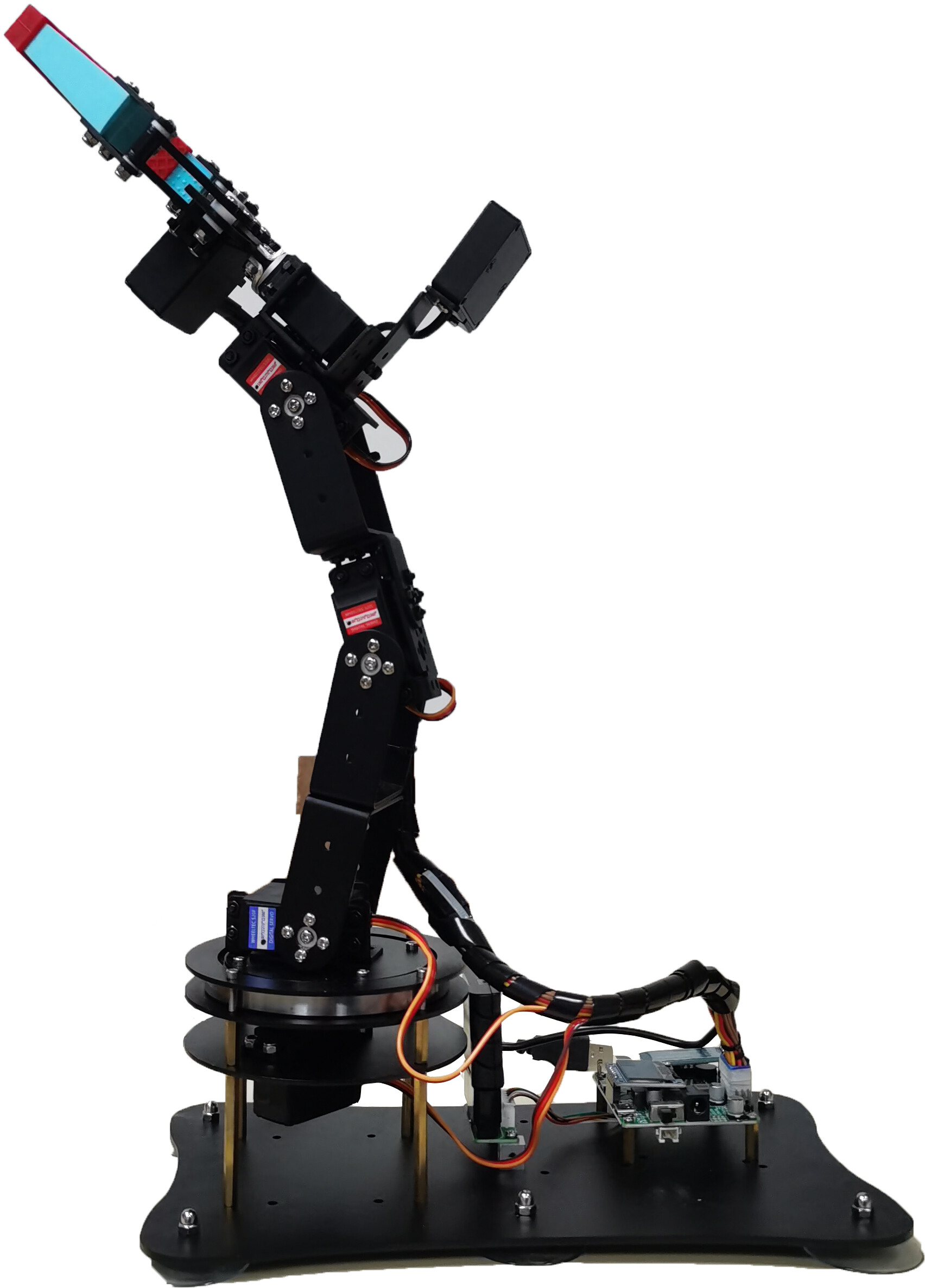
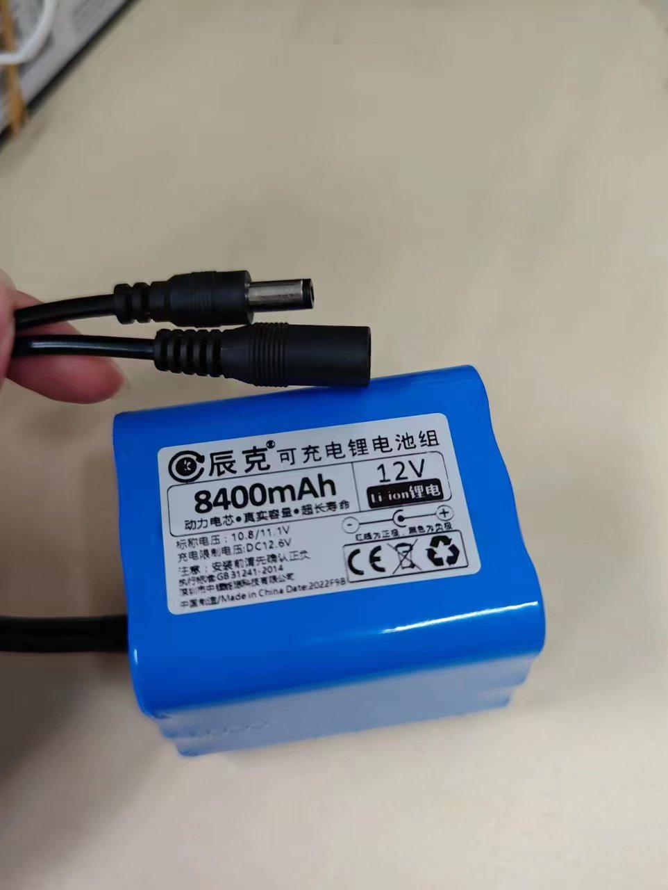
Additional use of 12V5A lithium battery for power supply
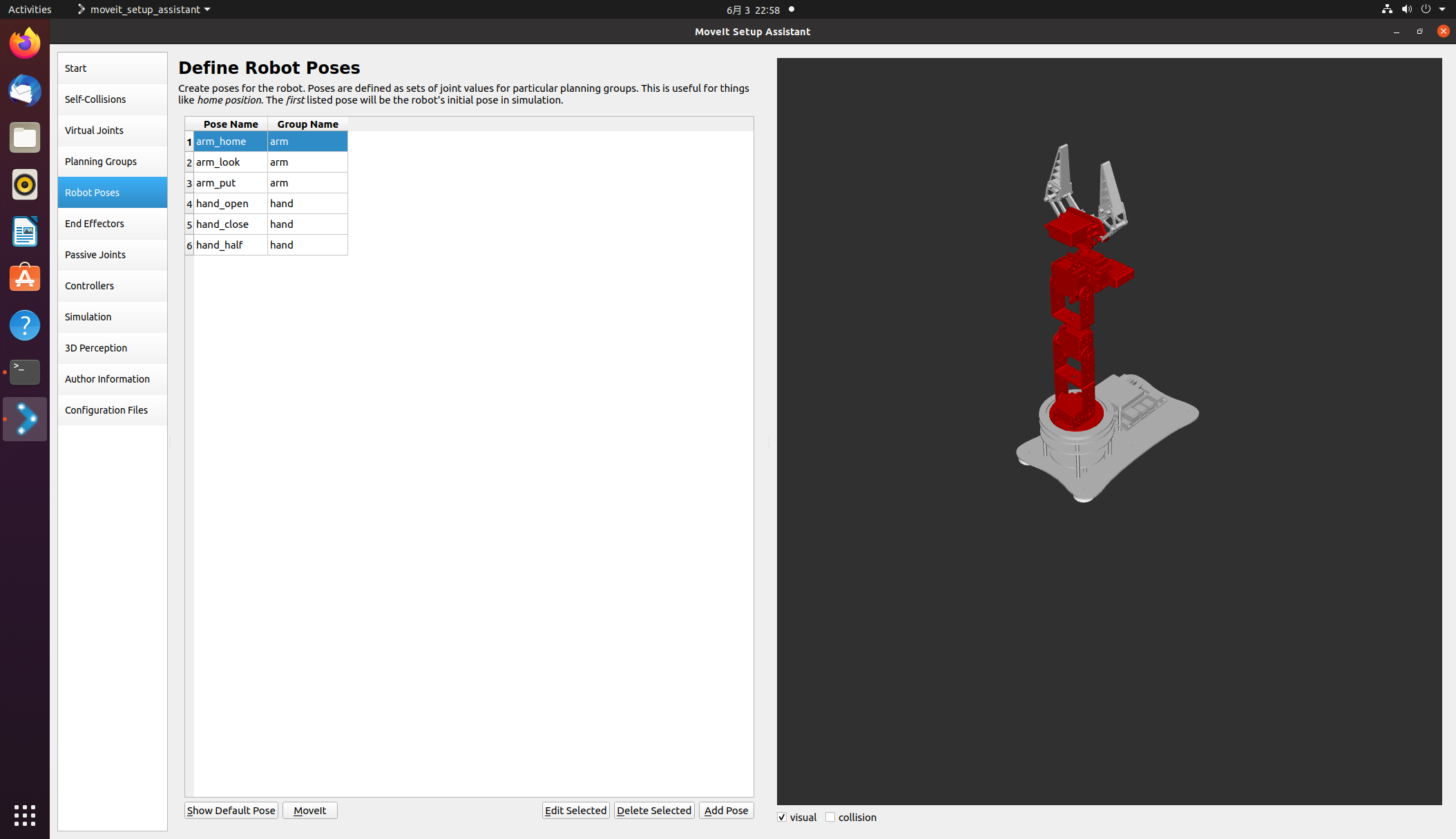
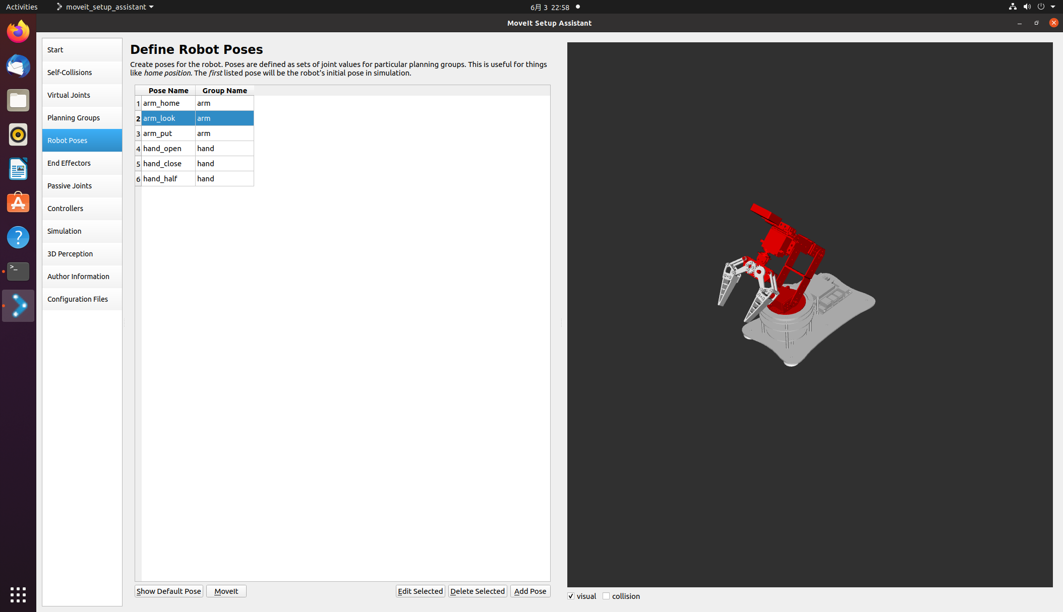
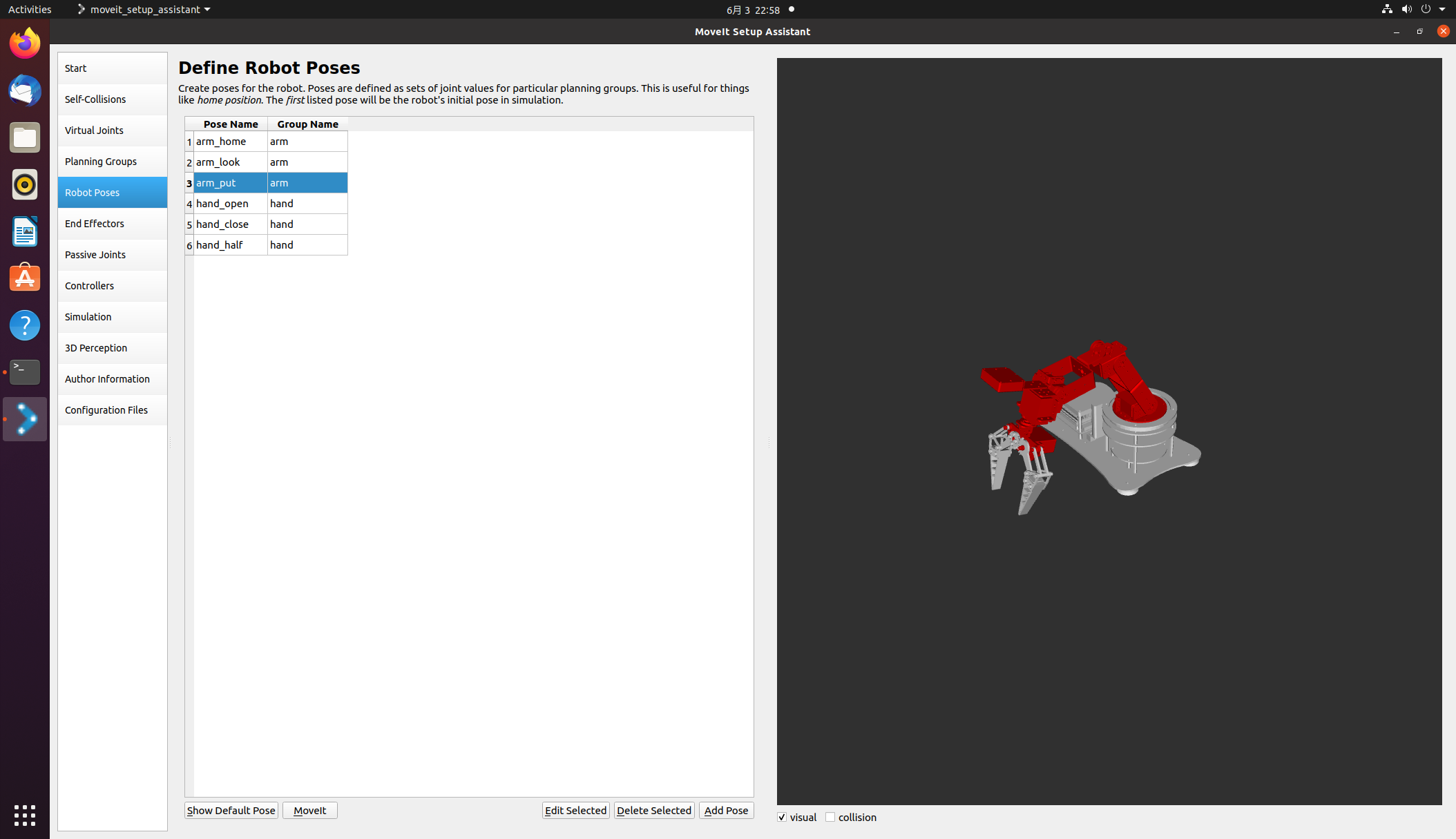
Missing degrees of freedom on the x-axis, But it’s usually enough to grab some daily necessities on the car Using the model provided by the seller Firstly, open Moveit to configure some initial poses of the robotic arm I have preset three robotic arm postures and three gripper postures respectively They are arm_home, arm_put, and arm_put, respectively (/API/v1/static/imgData/1685804276585. gif)!
Then there is the self written inverse solution program for the robotic arm (referred to here) https://blog.csdn.net/howard789/article/details/122120720 )
#!/usr/bin/env python3
# -*- coding: utf-8 -*-
import rospy, sys
import moveit_commander
import math

from moveit_commander import MoveGroupCommander
from geometry_msgs.msg import Pose
from copy import deepcopy

# P = 6.7
pi = math.pi
A1 = 10.5
A2 = 10.5
A3 = 10.5
A4 = 17.5
MAX_LEN = A2+A3+A4
MAX_HIGH = A1+A2+A3+A4

def cos(degree):
    return math.cos(math.radians(degree))

def sin(degree):
    return math.sin(math.radians(degree))


def atan2(v1,v2):
    rad=math.atan2(v1,v2)
    return math.degrees(rad)

def backward_kinematics(x, y, z,alpha):
    # len = math.sqrt(x*x + (P+y)*(P+y))
    j1 = math.atan2( x, y)
    x = abs(x)
    y = abs(y)
    len = math.sqrt(x*x + y*y)
    # print (len)
    high = z
    if len > MAX_LEN or high > MAX_HIGH:
        print ('超出范围')
        return 0,0,0,0

    L = len - A4*sin(alpha)
    H = high - A4*cos(alpha) - A1
    # print('L',L)
    # print('H',H)
    # print ((L*L + H*H - A2*A2 - A3*A3 )/(2 * A2 * A3))
    j3 = math.acos((L*L + H*H - A2*A2 - A3*A3 )/(2 * A2 * A3))
    K1 = A2 + A3*math.cos(j3)
    # print('K1',K1)
    K2 = A3*math.sin(j3)
    # print('K2',K2)
    W = math.atan2(K2, K1)
    # print('W',W)
    # print('math.atan(L/H)',math.atan(L/H))
    j2 = math.atan2(L,H) - W
    # print (math.radians(alpha))
    j4 = math.radians(alpha) - j2 - j3

    return j1,j2,j3,j4

def test_ok(x,y,z):
    for alpha in range(90,180):
        deg1, deg2, deg3, deg4 = backward_kinematics(x, y, z, alpha)
        if (deg1 < (0-pi/2)) or (deg1 > pi/2) or (deg2 < 0) or (deg2 > pi/2) or (deg3 < 0) or (deg3 > pi/2) or (deg4 < (0 - pi/4)) or (deg4 > pi/2):
            # print (deg1, deg2, deg3, deg4)
            alpha = alpha + 1
            print (alpha)
        else:
            print ([deg1, -deg2, -deg3, -deg4])
            return [deg1, 0, 0, 0, 0], [deg1, -deg2, -deg3, -deg4, 0]

class MoveItFkDemo:
    def __init__(self):
        print(rospy.has_param('/x'))
        #  此处使用launch文件启动的话可以在launch文件里面传入xyz参数,
        # 如果不用launch文件启动的话可以直接在下面改写xyz坐标
        x = rospy.get_param('x') #  获取参数
        y = rospy.get_param('y')
        z = rospy.get_param('z')

        # 初始化move_group的API,出现roscpp是因为底层是通过C++进行实现的
        moveit_commander.roscpp_initialize(sys.argv)

        # 初始化ROS节点,节点名为'moveit_fk_demo'
        rospy.init_node('moveit_fk_demo', anonymous=True)

        # 初始化需要使用move group控制的机械臂中的arm group
        arm = moveit_commander.MoveGroupCommander('arm')
        hand = moveit_commander.MoveGroupCommander('hand')
        # 设置机械臂运动的允许误差值,单位弧度
        arm.set_goal_joint_tolerance(0.01)

        # 设置允许的最大速度和加速度,范围0~1
        arm.set_max_acceleration_scaling_factor(0.5)
        arm.set_max_velocity_scaling_factor(0.5)

        # 控制机械臂先回到初始化位置,home是setup assistant中设置的
        arm.set_named_target('arm_home')
        arm.go()  #让机械臂先规划,再运动,阻塞指令,直到机械臂到达home后再向下执行
        hand.set_named_target('hand_open')
        hand.go()
        rospy.sleep(1)
        arm.set_named_target('arm_look')
        arm.go()
        rospy.sleep(5)
        #deticate
        # for i in range (2):
            # 设置机械臂的目标位置,使用4轴的位置数据进行描述(单位:弧度)
            # joint_positions =  [0.7853981633974483, -0.011235602203205963, -0.8998130107703047, -1.4102392921789475, 0]
        joint_positions1, joint_positions2 = test_ok(x,y,z)
        arm.set_joint_value_target(joint_positions1)  #设置关节值作为目标值

        # 控制机械臂完成运动
        arm.go()   # 规划+执行
        rospy.sleep(1)
        arm.set_joint_value_target(joint_positions2)
        arm.go()   # 规划+执行
        rospy.sleep(1)
        hand.set_named_target('hand_half')
        hand.go()
        rospy.sleep(1)
        arm.set_named_target('arm_look')
        arm.go()
        rospy.sleep(1)
        arm.set_named_target('arm_put')
        arm.go()
        rospy.sleep(1)
        hand.set_named_target('hand_open')
        hand.go()
        rospy.sleep(1)
        arm.set_named_target('arm_home')
        arm.go()
        rospy.sleep(1)
        # print (i)

        # 控制机械臂先回到初始化位置
        arm.set_named_target('arm_put')
        arm.go()
        rospy.sleep(1)

        arm.set_named_target('arm_home')
        arm.go()  #让机械臂先规划,再运动,阻塞指令,直到机械臂到达home后再向下执行
        rospy.sleep(1)
        # 关闭并退出moveit
        moveit_commander.roscpp_shutdown()
        moveit_commander.os._exit(0)

if __name__ == "__main__":
    try:
        MoveItFkDemo()
    except rospy.ROSInterruptException:
        pass
Combining yolov5 recognition in the official Horizon routine with binocular ranging (/API/v1/static/imgData/1685805340614. png)
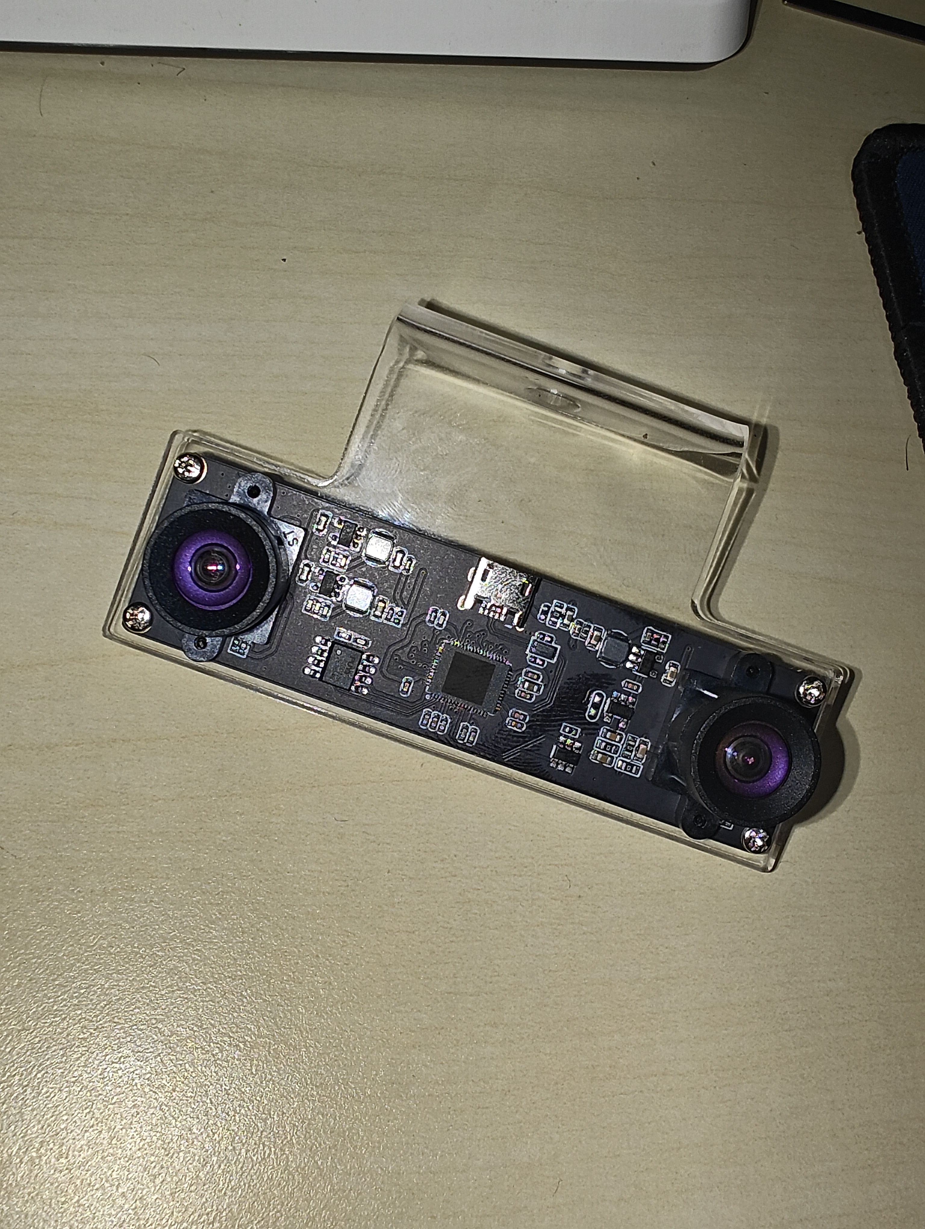
This is my binocular camera, about 200 yuan, which should be a bit cheaper. At that time, I was lazy mainly because of laboratory reimbursement, so I didn’t compare prices much. The code here was modified in conjunction with yolov5 in the official Horizon routine The part with the xmd field inside is the binocular ranging part that I added
This is my binocular camera, about 200 yuan, which should be a bit cheaper. At that time, I was lazy mainly because of laboratory reimbursement, so I didn’t compare prices much. The code here was modified in conjunction with yolov5 in the official Horizon routine The part with the xmd field inside is the binocular ranging part that I added
import numpy as np
import cv2
import os
from hobot_dnn import pyeasy_dnn as dnn
from bputools.format_convert import imequalresize, bgr2nv12_opencv

import lib.pyyolotools as yolotools

#xmd  vvvvvvvvvv
import stereoconfig_040_2 #导入相机内参

#xmd  ^^^^^^^^^^

def get_hw(pro):
    if pro.layout == "NCHW":
        return pro.shape[2], pro.shape[3]
    else:
        return pro.shape[1], pro.shape[2]

def format_yolov5(frame):
    row, col, _ = frame.shape
    _max = max(col, row)
    result = np.zeros((_max, _max, 3), np.uint8)
    result[0:row, 0:col] = frame
    return result

#xmd  vvvvvvvvvv
def undistortion(image, camera_matrix, dist_coeff):
    undistortion_image = cv2.undistort(image, camera_matrix, dist_coeff)

    return undistortion_image

# 获取畸变校正和立体校正的映射变换矩阵、重投影矩阵
# @param:config是一个类,存储着双目标定的参数:config = stereoconfig.stereoCamera()
def getRectifyTransform(height, width, config):
    # 读取内参和外参
    left_K = config.cam_matrix_left
    right_K = config.cam_matrix_right
    left_distortion = config.distortion_l
    right_distortion = config.distortion_r
    R = config.R
    T = config.T

    # 计算校正变换
    R1, R2, P1, P2, Q, roi1, roi2 = cv2.stereoRectify(left_K, left_distortion, right_K, right_distortion,
                                                    (width, height), R, T, alpha=0)

    map1x, map1y = cv2.initUndistortRectifyMap(left_K, left_distortion, R1, P1, (width, height), cv2.CV_32FC1)
    map2x, map2y = cv2.initUndistortRectifyMap(right_K, right_distortion, R2, P2, (width, height), cv2.CV_32FC1)

    return map1x, map1y, map2x, map2y, Q

# 畸变校正和立体校正
def rectifyImage(image1, image2, map1x, map1y, map2x, map2y):
    rectifyed_img1 = cv2.remap(image1, map1x, map1y, cv2.INTER_AREA)
    rectifyed_img2 = cv2.remap(image2, map2x, map2y, cv2.INTER_AREA)

    return rectifyed_img1, rectifyed_img2
# 立体校正检验----画线
def draw_line(image1, image2):
    # 建立输出图像
    height = max(image1.shape[0], image2.shape[0])
    width = image1.shape[1] + image2.shape[1]

    output = np.zeros((height, width, 3), dtype=np.uint8)
    output[0:image1.shape[0], 0:image1.shape[1]] = image1
    output[0:image2.shape[0], image1.shape[1]:] = image2

    # 绘制等间距平行线
    line_interval = 50  # 直线间隔:50
    for k in range(height // line_interval):
        cv2.line(output, (0, line_interval * (k + 1)), (2 * width, line_interval * (k + 1)), (0, 255, 0), thickness=2, lineType=cv2.LINE_AA)

    return output
# 视差计算
def stereoMatchSGBM(left_image, right_image, down_scale=False):
    # SGBM匹配参数设置
    if left_image.ndim == 2:
        img_channels = 1
    else:
        img_channels = 3
    blockSize = 3
    paraml = {'minDisparity': 0,
             'numDisparities': 128,
             'blockSize': blockSize,
             'P1': 8 * img_channels * blockSize ** 2,
             'P2': 32 * img_channels * blockSize ** 2,
             'disp12MaxDiff': 1,
             'preFilterCap': 63,
             'uniquenessRatio': 15,
             'speckleWindowSize': 100,
             'speckleRange': 1,
             'mode': cv2.STEREO_SGBM_MODE_SGBM_3WAY
             }

    # 构建SGBM对象
    left_matcher = cv2.StereoSGBM_create(**paraml)
    paramr = paraml
    paramr['minDisparity'] = -paraml['numDisparities']
    right_matcher = cv2.StereoSGBM_create(**paramr)

    # 计算视差图
    size = (left_image.shape[1], left_image.shape[0])
    if down_scale == False:
        disparity_left = left_matcher.compute(left_image, right_image)
        disparity_right = right_matcher.compute(right_image, left_image)

    else:
        left_image_down = cv2.pyrDown(left_image)
        right_image_down = cv2.pyrDown(right_image)
        factor = left_image.shape[1] / left_image_down.shape[1]

        disparity_left_half = left_matcher.compute(left_image_down, right_image_down)
        disparity_right_half = right_matcher.compute(right_image_down, left_image_down)
        disparity_left = cv2.resize(disparity_left_half, size, interpolation=cv2.INTER_AREA)
        disparity_right = cv2.resize(disparity_right_half, size, interpolation=cv2.INTER_AREA)
        disparity_left = factor * disparity_left
        disparity_right = factor * disparity_right

    # 真实视差(因为SGBM算法得到的视差是×16的)
    trueDisp_left = disparity_left.astype(np.float32) / 16.
    trueDisp_right = disparity_right.astype(np.float32) / 16.

    return trueDisp_left, trueDisp_right
#xmd  ^^^^^^^^^^

# img_path 图像完整路径
# img_path = '/home/sunrise/codes/test_yolov5/left_0.jpg'
# model_path 量化模型完整路径
model_path = '/home/sunrise/codes/test_yolov5/yolov5s.bin'
# 类别名文件
classes_name_path = 'coco_classes.names'
# 设置参数
thre_confidence = 0.4
thre_score = 0.25
thre_nms = 0.45
# 框颜色设置
colors = [(255, 255, 0), (0, 255, 0), (0, 255, 255), (255, 0, 0)]

# 1. 加载模型,获取所需输出HW
models = dnn.load(model_path)
model_h, model_w = get_hw(models[0].inputs[0].properties)
print(model_h, model_w)

# 2 加载图像,根据前面模型,转换后的模型是以NV12作为输入的
# 但在OE验证的时候,需要将图像再由NV12转为YUV444

# imgOri = cv2.imread(img_path) #预设图像
# 或者拍照
camera = cv2.VideoCapture(8)
print(camera.isOpened())
camera.set(cv2.CAP_PROP_FRAME_WIDTH,2560)
camera.set(cv2.CAP_PROP_FRAME_HEIGHT,720)
ret, imgOri = camera.read()

inputImage = format_yolov5(imgOri[0:720, 0:1280])
img = imequalresize(inputImage, (model_w, model_h))
nv12 = bgr2nv12_opencv(img)

# 3 模型推理
t1 = cv2.getTickCount()
outputs = models[0].forward(nv12)
t2 = cv2.getTickCount()
outputs = outputs[0].buffer # 25200x85x1
print('time consumption {0} ms'.format((t2-t1)*1000/cv2.getTickFrequency()))

# 4 后处理
image_width, image_height, _ = inputImage.shape
fx, fy = image_width / model_w, image_height / model_h
t1 = cv2.getTickCount()
class_ids, confidences, boxes = yolotools.pypostprocess_yolov5(outputs[0][:, :, 0], fx, fy,
                                                            thre_confidence, thre_score, thre_nms)
t2 = cv2.getTickCount()
print('post consumption {0} ms'.format((t2-t1)*1000/cv2.getTickFrequency()))

#xmd  vvvvvvvvvv
i = 3
string = 're'
image_left = imgOri[0:720, 0:1280] #左图
image_right = imgOri[0:720, 1280:2560]  #右图
height, width = image_left.shape[0:2]
print("width = %d \n"  % width)
print("height = %d \n" % height)
#读取相机内参
config = stereoconfig_040_2.stereoCamera()
#立体校正
map1x, map1y, map2x, map2y, Q = getRectifyTransform(height, width, config)  # 获取用于畸变校正和立体校正的映射矩阵以及用于计算像素空间坐标的重投影矩阵
print('Q',Q)
iml_rectified, imr_rectified = rectifyImage(image_left, image_right, map1x, map1y, map2x, map2y)

line = draw_line(iml_rectified, imr_rectified)
# print('./%s检验%d.png' %(string,i), line)
cv2.imwrite('./%s检验%d.png' %(string,i), line)
iml = undistortion(image_left, config.cam_matrix_left, config.distortion_l)
imr = undistortion(image_right, config.cam_matrix_right, config.distortion_r)
iml_rectified_l, imr_rectified_r = rectifyImage(iml, imr, map1x, map1y, map2x, map2y)
disp, _ = stereoMatchSGBM(iml_rectified_l, imr_rectified_r, True)
# print('./%s视差%d.png' %(string,i), disp)
cv2.imwrite('./%s视差%d.png' %(string,i), disp)
# 计算像素点的3D坐标(左相机坐标系下)
points_3d = cv2.reprojectImageTo3D(disp, Q)  # 可以使用上文的stereo_config.py给出的参数
#xmd  ^^^^^^^^^^

# 5 绘制检测框
with open(classes_name_path, "r") as f:
    class_list = [cname.strip() for cname in f.readlines()]
t1 = cv2.getTickCount()
list = []
for (classid, confidence, box) in zip(class_ids, confidences, boxes):
    color = colors[int(classid) % len(colors)]
    cv2.rectangle(imgOri, box, color, 2)
    # cv2.rectangle(img, (xmin, ymin), (xmax, ymax), (0,0,255), 2)
    # xmin = box[0],ymin = box[1] - 20
    cv2.rectangle(imgOri, (box[0], box[1] - 20), (box[0] + box[2], box[1]), color, -1)
    cv2.putText(imgOri, class_list[classid], (box[0], box[1] - 10), cv2.FONT_HERSHEY_SIMPLEX, .5, (0,0,0))
    print("box[0]",box[0],"box[1]",box[1],"box[2]",box[2],"class_list[classid]",class_list[classid])
    x = int((box[0]+box[2]+box[0])/2)
    y = int((box[1]+box[3]+box[1])/2)
    print('点 (%d, %d) 的三维坐标 (%f, %f, %f)' % (x, y, points_3d[y, x, 0]/10, points_3d[y, x, 1]/10, points_3d[y, x, 2]/10))
    dis = ( (points_3d[y, x, 0] ** 2 + points_3d[y, x, 1] ** 2 + points_3d[y, x, 2] **2) ** 0.5) / 1000
    print('点 (%d, %d) 距离左摄像头的相对距离为 %0.3f m' %(x, y, dis) )
    if dis <= 10:
        print(classid+1)
        print(round(points_3d[y, x, 0]/10,2))
        print(round(points_3d[y, x, 1]/10,2))
        print(round(points_3d[y, x, 2]/10,2))
        list.append([classid+1,round(points_3d[y, x, 0]/10,2),round(points_3d[y, x, 1]/10,2),round(points_3d[y, x, 2]/10,2),round(dis,2)])
t2 = cv2.getTickCount()
print('draw rect consumption {0} ms'.format((t2-t1)*1000/cv2.getTickFrequency()))
print(list[0][0])
cv2.imwrite('res.png', imgOri)
Among them, stereoconfig_040_2. py is the camera calibration file, The values are from the calibration results of Matlab, please refer to my own
import numpy as np


####################仅仅是一个示例###################################


# 双目相机参数
class stereoCamera(object):
    def __init__(self):
        # 左相机内参
#         1051.11659064493	0	0
# -1.89879698679960	1049.84130477950	0
# 634.619437827553	493.773368290712	1
        self.cam_matrix_left = np.array([   [1051.1166,   -1.8988,  634.6194],
                                            [       0,  1049.8413,  493.7734],
                                            [       0,         0,         1]
                                        ])
        # 右相机内参
#         1051.83160192579	0	0
# -2.02039911612483	1047.22197211167	0
# 664.795908482304	510.350394680884	1
        self.cam_matrix_right = np.array([  [1051.8316,   -2.0204,  664.7959],
                                            [       0,  1047.2220,  510.3504],
                                            [       0,         0,         1]
                                        ])

        # 左右相机畸变系数:[k1, k2, p1, p2, k3] [-0.013781963314708,0.053508639384062,[-0.001767389944871,0.008806335095328],0.207695529605878]
        self.distortion_l = np.array([[-0.0212, 0.1042, -0.0020, 0.0059, 0.4863]])
        self.distortion_r = np.array([[-0.0138, 0.0535, -0.0018, 0.0088, 0.2077]])

        # 旋转矩阵
#         0.999980864653300	0.000221501479809274	0.00618233486092491
# -0.000298314433637631	0.999922744426069	0.0124264310216711
# -0.00617910476823695	-0.0124280375173278	0.999903676634770
        self.R = np.array([ [      1,  -0.0003, -0.0062],
                            [0.0002,  1.0000, -0.0124],
                            [ 0.0061,  0.0124,  1.0000]
                            ])

        # 平移矩阵[-60.826943209894390,0.092931782588213,-2.177973655721749]
        self.T = np.array([[-60.8269], [0.0929], [-2.1780]])

        # 焦距1051.11659064493
        self.focal_length = 1051.1166 # 默认值,一般取立体校正后的重投影矩阵Q中的 Q[2,3]

        # 基线距离
        self.baseline = 60.8269 # 单位:mm, 为平移向量的第一个参数(取绝对值)
To stitch two together, it was necessary to calibrate the camera and robotic arm, but it was not successful. Therefore, I resorted to brute force and directly measured the inclination angle between the camera coordinates and the robotic arm base coordinates. Then, I solved the problem of transferring the target from the camera coordinate system to the robotic arm base coordinates. The effect is as shown in the picture:
! [Grab. gif] Upload attachments with a size limit of 10m. I’m not sure if I can see this animated image! [Grab. png] And here’s a static screenshot